Products
Other
-
Online Customer Service
Company
TEL031)
491-5311FAX031)
492-0473
Light Rail System 
Runway Rail
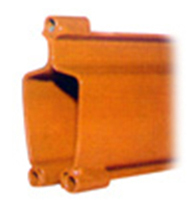
HLR-I
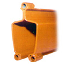
HLR-II
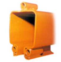
HLR-III
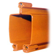
HLR-IV
| 2000 |
| 3000 |
| 4000 |
| 5000 |
| 6000 |
| HLR-I | HLR-II | HLR-III | HLR-IV | ||||
|---|---|---|---|---|---|---|---|
| Type | Weight(Kg) | Type | Weight(Kg) | Type | Weight(Kg) | Type | Weight(Kg) |
| HLR-I 2000-2 |
13.6 | HLR-II 2000-2 |
17.4 | HLR-III 2000-2 |
27.6 | HLR-IV 2000-2 |
34.6 |
| HLR-I 2000-2 |
13.6 | HLR-II 2000-2 |
17.4 | HLR-III 2000-2 |
27.6 | HLR-IV 2000-2 |
34.6 |
| HLR-I 4000-2 |
27.2 | HLR-II 4000-2 |
34.8 | HLR-III 4000-2 |
55.2 | HLR-IV 4000-2 |
69.2 |
| HLR-I 5000-2 |
34.0 | HLR-II 5000-2 |
43.5 | HLR-III 5000-2 |
69.0 | HLR-IV 5000-2 |
86.5 |
| HLR-I 6000-2 |
40.8 | HLR-II 6000-2 |
52.2 | HLR-III 6000-2 |
82.8 | HLR-IV 6000-2 |
103.8 |
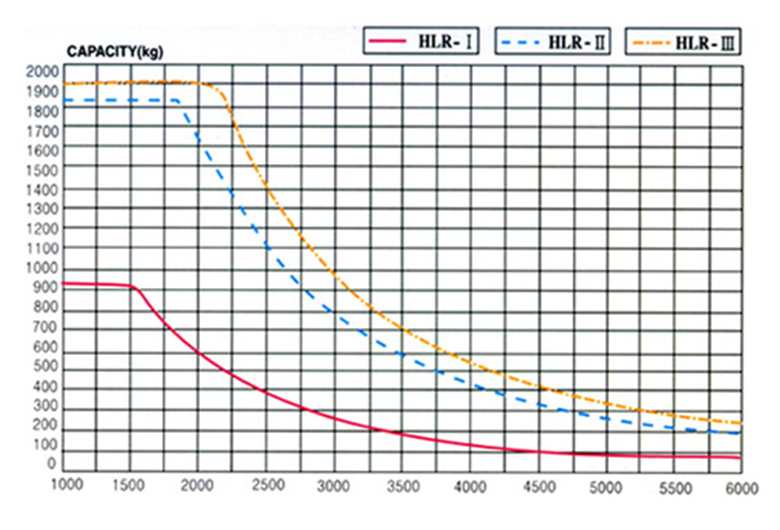
HLR Rail span wersus capacity
| image | µ | X | Y | Weight (Kg) | |
|---|---|---|---|---|---|
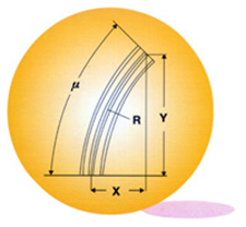 |
HLR-III R=1500 |
15° | 52 | 396 | 4.7 |
| 30° | 204 | 762 | 9.6 | ||
| 45° | 446 | 1078 | 14.3 | ||
| HLR-I R=900 |
15° | 31 | 236 | 1.4 | |
| 30° | 125 | 456 | 2.8 | ||
| 45° | 268 | 646 | 4.2 | ||
| 60° | 457 | 792 | 5.6 | ||
Bridge Rail
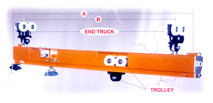
A-B Rail |
HLR-I | HLR-II | HLR-III | HLR-IV |
|---|---|---|---|---|
| 1000 - 300 | HLR 11000 | HLR 21000 | HLR 11000 | HLR 21000 |
| 2000 - 1300 | HLR 12000 | HLR 22000 | HLR 12000 | HLR 22000 |
| 3000 - 2300 | HLR 13000 | HLR 23000 | HLR 13000 | HLR 23000 |
| 4000 - 3300 | HLR 14000 | HLR 24000 | HLR 14000 | HLR 24000 |
| 5000 - 4300 | HLR 15000 | HLR 25000 | HLR 15000 | HLR 25000 |
| 6000 - 5300 | HLR 16000 | HLR 26000 | HLR 16000 | HLR 26000 |
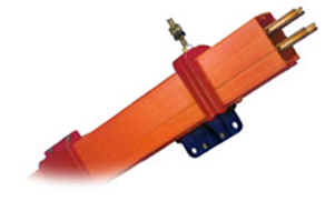
Power Supply System
Power Supply System - Duct bar system
-
Features
- Hoist, Over Head Crane, Monorail, Puller (Cart), Conveyor Line, Aging Circuit, Auto Warehouse
- Device that safely supplies power to other power source rails such as actuators
- Resolves issues such as collector deviation, bus-bar corrosion, defective connection, etc.
- Removed electric risk factors through complete insulation of all parts used
- Can be used in poor environments (dust, humidity, corrosion) or extreme (high/low temperatures) conditions
- Simple transportation and installation with light and simple assembly method
- Permanent parts giving it semi-permanent life
- No maintenance costs or insulation facility costs
Parts
- 1. Collector
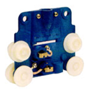
- 2. Hanger Clamp
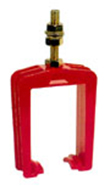
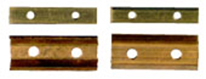
- 3. Joint Keeper
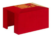
- 4. End Cap
- 5. Joint Cover
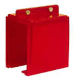
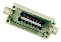
- 6. Power Feed Box
Installation Method
-
1. General
-
a. Bracket installation
The materials for brackets are angles and select the intervals for attaching the brackets in proportion to the cart drive speed.
- b. When attaching the Hanger Clamp to the Bracket, attach by aligning horizontal and vertical.
-
c. Duct insertion and conductor connection
- Ⅰ. When inserting Duct into the Hanger Clamp, make sure that the groove on one side is continuously in a straight line. If the groove is connected zig-zag, the Collecting Trolley cannot be activated in the Duct.
- Ⅱ. When end feeding power in one end, the standard length of 4m Duct should be inserted in the Hanger Clamp while connecting the conductor and conductor to the Rail Connector and then assemble the connection part with a Joint Keeper.
- Ⅲ. When attaching the Rubber Covering, it must be assembled in the groove where the Rubber Covering will be attached.
- Ⅳ. For center feeding of power, insert in the duct with the center feed box first where power is supplied, and then insert duct to one direction or both directions and connect with Joint Keeper.
- Ⅴ. Insert Collector inside the Duct where the cart is stopped and connect completely Duct completely according to the needed length and then attach End Cap on one side or both side ends.
-
d. Fastening Towing Trolley Arm and installing support
- Ⅰ. In order to attach the Towing Trolley Arm needed to move the Collector operated inside the Duct, manufacture and install by welding or assembly support for the moving cart.
- Ⅱ. When fastening Towing Trolley Arm to support, fasten to locate about 3cm below the hole of the Collector inserted inside the Duct.
-
e. Power connection
After completing all work, connect power to End Feed Box or Center Feed Box from the power supply part and complete installation with testing.
-
a. Bracket installation
-
2. Checklist
- a. Is the duct installed in alignment with the driving rail and being horizontal and vertical?
- b. Is the Hanger Clamp installed so that there is slipping when there is fine contraction due to changes in the surrounding temperature of the Duct?
- c. Is the Duct’s groove made in a continuous line?
- d. Are there any obstacles in the area when the Collector moves?
Power Supply System - Trolley bar system
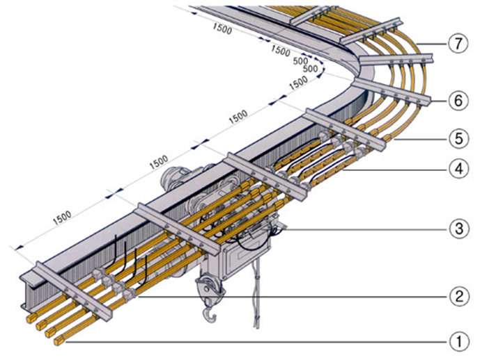
Trolley Bar Configuration
| No. | Item Name | No. | Item Name |
|---|---|---|---|
| 1 | End Cap | 5 | Joint Cover |
| 2 | Power Feeder | 6 | Hanger Clamp |
| 3 | Collector | 7 | Trolley Bar |
| 4 | Expansion Section |
Type
| Allowed current (A) | Length (mm) | Material |
|---|---|---|
| 60A | 3,000 | Galvanized Steel (100%) |
| 90A | 3,000 | G. I. (75%), Cu (25%) |
| 160A | 3,000 | SUS (50%), Cu (50%) |
| 200A | 3,000 | G. I. (50%), Cu (50%) |
| 300A | 3,000 | Copper |
| 500A | 3,000 | Solid Copper |
- Installation Method
- Fasten Hanger Clamp on bracket.
- Insert Trolley Bar in the Hanger Clamp. However, if there is a rotating part, insert this part first.
- Combine inserted Trolley Bar to connected tool.
- Attach Trolley Bar 160A, 200A, 300A, and 500A to connection terminal and cover with Joint Cover at the joints.
- Cut sheath of Trolley Bar and expose conductor as much as the rated length.
- Attach power Feeder and connect power cord.
- Cover with covering to insulate power input part.
- Cut the remaining Trolley Bar and cover with End Cap.
- Install by making sure the distance between the Collector’s Mountain Bar center and Trolley Bar collector (carbon brush) contact area is 90mm.
- Make final inspection for test run and then perform test run.